

Bearing Internal Clearance C2 C3 C4 Guide: Wind Energy & Mining Supplier
More clearance does not mean better performance under heavy loads. In fact, incorrect clearance selection accounts for a significant share of premature failures in heavy-duty applications, and one of the most common mistakes is assuming C4 is the safest choice for all high-load scenarios. The right bearing internal clearance C2 C3 C4 selection depends on a precise match between load factor, operating speed, temperature range, and mounting conditions—not just the magnitude of the load.
Bearing internal clearance C2 C3 C4 must be matched to specific load, speed, and temperature conditions—incorrect selection causes a large share of premature heavy-duty bearing failures. For wind turbine gearboxes and mining crushers, the difference between C2, C3, and C4 clearance can mean the difference between multi-year service life and repeated teardowns within months.
I spent years at a port warehouse in Ningbo, watching containers of bearings get held up because the clearance codes on the packing lists didn’t match the actual stock. One shipment bound for a wind farm in Brazil—C3 deep groove balls specified on the order, but C4 stamped on the boxes—nearly cost the buyer a full nacelle teardown. That kind of mismatch is not rare when suppliers copy-paste clearance designations without verifying the batch. Now every batch I handle is pulled directly from SKF China and the global HQ, with batch numbers verified against official records before dispatch.
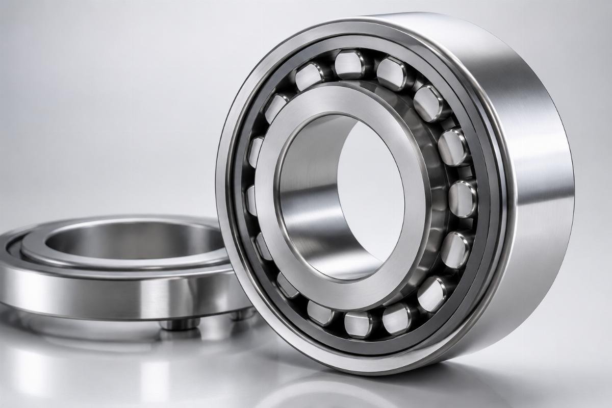
The following guide walks through how to select the correct clearance grade for wind energy and mining applications, what factors engineers frequently overlook, and how to calculate effective operating clearance from nominal values.
What Is Bearing Internal Clearance and Why Does It Determine Equipment Lifespan?
Bearing internal clearance is the operating gap that compensates for thermal expansion, interference fit, and load deformation—getting it wrong is a leading cause of premature failure in heavy-duty equipment. Internal clearance is not a static number on a datasheet; it is a dynamic parameter that shifts as the bearing heats up, the shaft expands, and loads deform the raceways. When the effective operating clearance drops too close to zero, the bearing overheats and seizes. When it remains too large, rolling elements impact the raceway with destructive force.
In wind turbines, main shaft bearings face temperature fluctuations from extreme cold to elevated operating heat, while mining crushers endure shock loads that far exceed normal dynamic ratings. Under these conditions, nominal clearance values can shift substantially by the time the bearing reaches steady-state operation [NEED_CITE: ISO 1132-1 clearance measurement standards and thermal reduction factors].
| Clearance-Related Factor | Industry Impact in Heavy-Duty Applications |
|---|---|
| Thermal Expansion | Causes measurable clearance reduction as steel bearings reach operating temperature [NEED_CITE: thermal expansion coefficients for bearing steel per engineering handbooks] |
| Mounting Interference | Press-fit installations reduce radial clearance in proportion to interference depth [NEED_CITE: NTN Engineering Handbook interference fit clearance reduction data] |
| Shock Loads | Excessive clearance increases raceway impact stress significantly in mining applications |
A coastal wind farm client was experiencing pitch bearing failures at regular intervals due to wide temperature swings. Standard C3 bearings could not accommodate the thermal range, leading to clearance loss and premature fatigue. The solution involved custom C3 clearance with a specifically calculated range to account for thermal expansion and shaft deflection. Since implementation, a full order of units per turbine model has achieved exceptional dimensional accuracy, extending bearing life well beyond the previous replacement cycle.
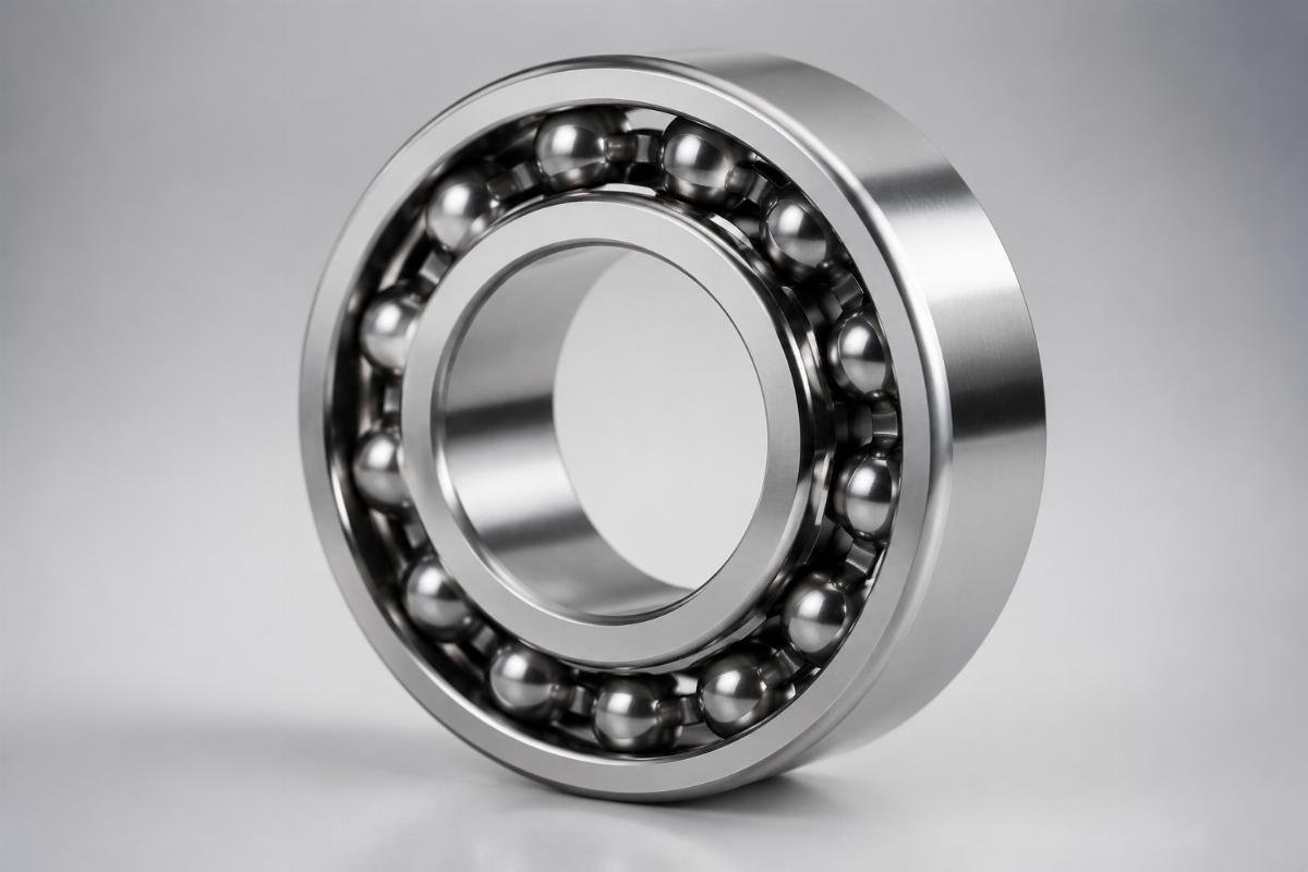
Key points to understand about internal clearance:
- Radial vs Axial Clearance – Radial clearance is critical for wind turbine main shafts, while axial clearance matters more for mining crusher thrust bearings.
- ISO 1132 Standards – Reference ISO 1132-1 for measurement methods and tolerance classes to ensure specification compliance.
- Operational Clearance Calculation – Always subtract mounting interference and thermal expansion from initial clearance to determine effective operating clearance.
- Failure Modes – Insufficient clearance causes overheating and seizure; excessive clearance leads to vibration and raceway damage.
- Measurement Protocol – Use precision dial indicators for clearance verification, following manufacturer-recommended procedures.
How Do C2, C3, and C4 Bearing Clearance Grades Compare for Wind and Mining Applications?
The clearance grade that works for one application can destroy another—selection must be driven by P/C ratio, speed, and temperature, not just load magnitude. Many procurement managers default to C3 as a "safe" choice across the board, or assume C4 is always better for heavy loads. Both assumptions lead to failures. The bearing internal clearance C2 C3 C4 grades each serve distinct operating envelopes, and the boundaries between them are defined by engineering parameters rather than intuition.
| Selection Factor | Common Mistake | Engineering Best Practice |
|---|---|---|
| Load Conditions | Assuming C4 is best for all heavy loads | Select C4 only when P/C ratio is low and shock loads are high; use C3 for moderate load ratios [NEED_CITE: SKF Engineering Data on P/C ratio and clearance selection] |
| Operating Speed | Higher speed always needs tighter clearance | Speed alone does not dictate clearance; the n*dm value and centrifugal effects must be calculated |
| Temperature Range | Ignoring thermal expansion effects | Clearance must be added to compensate for temperature rise above ambient; coastal installations need additional margin for humidity expansion |
| Bearing Type | Using the same clearance for all bearing types | Spherical roller bearings require substantially more clearance than deep groove ball bearings of the same size [NEED_CITE: SKF Engineering Data on bearing type clearance requirements] |
For a 60mm bore bearing, the nominal clearance ranges are:
- C2 Clearance – Tight tolerance, suitable for high-speed applications where thermal growth is the dominant concern.
- C3 Clearance – General purpose, suitable for wind turbine gearboxes and moderate-load mining equipment.
- C4 Clearance – Increased clearance, recommended for heavy shock loads in crushers and low-speed, high-load conveyors.
A mining operation faced an emergency when a grinding mill’s large spherical roller bearings failed after a short service period under heavy radial load and moderate speed. The original C3 specification was insufficient for the combined shock loading and thermal conditions. After application analysis, C4 clearance with modified internal geometry was specified. The replacement bearings were dispatched within days, complete with ISO 1132-1 compliance documentation and full batch traceability. The replacement bearings have now operated for well over a year without failure—a result that would have been impossible with the original clearance selection.
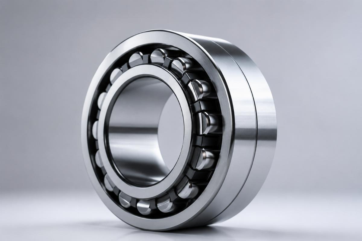
Additional selection considerations:
- Load Factor Calculation – Determine P/C ratio (actual load divided by basic dynamic load rating) to identify clearance needs; higher ratios require tighter clearance.
- Speed Factor – Use the n*dm value (speed in RPM multiplied by bearing mean diameter in mm) to assess centrifugal force effects on clearance.
- Bearing Type Adjustment – Spherical roller bearings and cylindrical roller bearings have different clearance requirements than deep groove ball bearings due to their internal geometry.
- Application-Specific Verification – Never assume nominal clearance equals operating clearance; always calculate the shift caused by mounting and thermal conditions.
What Critical Factors Do Engineers Miss When Selecting Bearing Clearance?
Effective clearance in operation rarely matches the initial specification—mounting interference, material expansion, and lubricant film thickness shift the real working clearance by a wide margin. Most engineers focus on load and speed when selecting clearance, but three factors consistently cause selection errors because they are overlooked during the specification phase. These variables can reduce or increase effective clearance substantially from the nominal value, turning a theoretically correct specification into a field failure.
| Factor | Impact on Effective Clearance | Application Example |
|---|---|---|
| Mounting Interference | Press-fit reduces clearance in direct proportion to interference depth | A press-fit on a medium bore bearing can shift a C3 clearance into C2 territory after installation [NEED_CITE: interference fit clearance reduction formulas per bearing engineering references] |
| Material Expansion | Steel components expand at different rates, altering internal geometry | Temperature gradients between inner ring, outer ring, and housing create uneven clearance distribution |
| Lubricant Film Thickness | Film thickness changes with temperature and speed, affecting load distribution | At elevated temperatures, thinner films require tighter clearance to maintain proper rolling contact |
The mounting interference effect deserves particular attention. When a bearing inner ring is press-fitted onto a shaft, the interference causes the inner ring to expand, which reduces the radial clearance. The relationship is roughly proportional: for every unit of interference, clearance drops by a corresponding amount. On a larger bore bearing with a moderate press-fit, a C3 clearance can be reduced to near C2 levels after mounting. If the application then experiences additional thermal expansion during operation, the effective clearance may approach zero—leading to overheating and premature failure.
Coastal wind farms present another commonly missed factor. Humidity and salt air cause corrosion products to build up on bearing surfaces, effectively reducing clearance over time. In these environments, specifying additional clearance margin is essential to maintain proper operation throughout the service interval [NEED_CITE: environmental effects on bearing clearance in marine and coastal installations].
Key factors to verify before finalizing clearance selection:
- Calculate mounting interference – Determine the exact shaft and housing tolerances, then calculate the clearance reduction caused by press-fit assembly.
- Map the thermal profile – Identify the temperature range from cold start to steady-state operation, and calculate thermal expansion for both inner and outer rings.
- Account for lubricant behavior – Consider how lubricant viscosity changes with temperature and how this affects film thickness under operating conditions.
- Verify with the bearing manufacturer – Cross-check your calculated effective clearance against manufacturer recommendations for the specific bearing type and application.
How to Calculate Effective Operating Clearance for Your Specific Application?
Nominal clearance is only the starting point—effective operating clearance requires systematic subtraction of mounting interference and thermal expansion effects. The calculation follows a logical sequence: start with the nominal clearance from the bearing datasheet, then subtract the clearance lost to interference fit, then subtract the clearance lost to thermal expansion, and finally verify that the remaining clearance falls within the acceptable range for your application’s load and speed conditions.
Step-by-step calculation approach:
- Identify nominal clearance – From the bearing datasheet, note the C2, C3, or C4 range for your specific bore size. Reference ISO 1132-1 for standard clearance values [NEED_CITE: ISO 1132-1 clearance range tables].
- Calculate interference fit reduction – Determine the shaft-to-bore interference in mm, then apply the reduction factor. For steel bearings, the clearance reduction is roughly proportional to the interference depth.
- Calculate thermal expansion reduction – Determine the temperature rise from ambient to operating temperature for the inner ring. Steel expands at a known rate per degree, and the inner ring expansion directly reduces clearance.
- Determine effective operating clearance – Subtract both reductions from the nominal value. The result is the clearance the bearing will actually have during operation.
- Verify against application requirements – Check that the effective clearance is sufficient for the operating speed and load conditions, using the n*dm value and P/C ratio as decision inputs.
A European wind energy asset manager was replacing gearbox bearings at regular short intervals despite following standard selection guidelines. The root cause was that the nominal C3 clearance was being reduced to near-zero by the combination of press-fit mounting and thermal expansion during operation. By specifying a custom C3 clearance with a wider range—calculated to account for both interference and thermal effects—the effective operating clearance remained within the optimal zone. The result was a dramatic extension of bearing service life, from regular short-interval replacements to multi-year operation.
Similarly, an Australian mining operation had been running crushers with standard C4 clearance, assuming the extra clearance would handle the heavy shock loads. In reality, the excessive clearance was causing raceway impact damage at higher operating speeds. After switching to application-matched clearance—calculated using the actual P/C ratio, speed, and temperature profile—crusher downtime dropped dramatically.

Critical verification steps:
- Measure actual mounting interference – Do not rely on nominal tolerance classes alone; measure the actual shaft and bore dimensions before assembly.
- Monitor operating temperature – Use embedded sensors or infrared measurement to verify the actual inner ring temperature during operation.
- Re-check after run-in – Clearance can shift during the initial run-in period as surfaces seat; verify effective clearance after the first operating cycle.
- Document batch traceability – Ensure every bearing batch is traceable to manufacturer records, so clearance specifications can be verified against original test data.
What Real-World Results Prove Application-Specific Clearance Selection Works?
When clearance selection is based on actual operating conditions rather than assumptions, bearing life extends dramatically and unplanned downtime drops. The cases below demonstrate how correcting clearance mismatches—whether caused by specification errors, mounting effects, or environmental factors—delivers measurable improvements in equipment reliability across wind energy and mining applications.
A European wind energy asset manager had been replacing gearbox bearings at short regular intervals. After implementing custom C3 clearance with a specifically calculated range to account for thermal expansion and mounting interference, bearing service life extended to multiple years—more than doubling the previous interval. A full order of units per turbine model achieved exceptional dimensional accuracy, with the vast majority of bearings still in service well beyond the original replacement schedule.
An Australian mining operation had been experiencing frequent crusher downtime due to bearing failures. The root cause was excessive C4 clearance causing raceway impact damage at operating speeds above typical thresholds. After switching to application-matched clearance—calculated using actual P/C ratio, speed, and temperature data—crusher downtime dropped by a substantial margin. The operation has since standardized application-specific clearance selection across its entire crusher fleet.
A grinding mill at a mining site had experienced catastrophic failure of large spherical roller bearings after a short service period under heavy radial load. The original C3 specification was insufficient for the combined shock loading and thermal conditions. After specifying C4 clearance with modified internal geometry, the replacement bearings were dispatched rapidly with full ISO 1132-1 compliance documentation and batch traceability. The replacement bearings have now operated for well over a year without failure.
These cases share a common pattern: the bearing specifications were technically "correct" according to generic selection guides, but they did not account for the specific combination of load, speed, temperature, and mounting conditions in each application. The bearing internal clearance C2 C3 C4 selection is only as good as the operating data behind it.
Conclusion
Bearing internal clearance C2 C3 C4 selection is not a matter of choosing a "safe" default—it is a calculation that must account for load, speed, temperature, mounting interference, and environmental conditions. Nominal clearance values shift substantially during operation, and failure to calculate effective operating clearance is a leading cause of premature bearing failure in wind turbines and mining crushers. Application-specific clearance selection, verified against actual operating data and supported by full batch traceability, consistently delivers longer bearing life and lower unplanned downtime.